Flatten Spectrum (Gain Equalization)
This module creates an inverse filter, starting from a generic Impulse Response, and inverting only the Minimum Phase component of it. This means that the Magnitude of the Transfer Function is inverted, and the inverse filter, applied to a signal containing the effect of the original impulse response, perfectly equalizes it in terms of spectral flatness.
It must be nothed, anyway, that the non-minimum phase component is left not-inverted: as this component carries the reverberation, the equalised signal has a proper spectral frequency response, but it still suffers of echoes or reverberation present in the original signal. Thus this module is ideal for creating an equalising filter taking into account only the direct wave coming from a loudspeaker with poor frequency response.
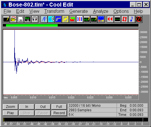
For example, suppose that we have measured the anechoic IR of a loudspeaker:
 |
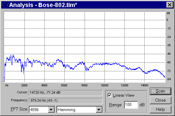
through CoolEdit we can look at its Frequency Response:
 |
Now we can press the Flatten Spectrum button, and the following Dialog Box appears:
 |
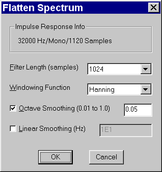 |
With this dialog box it is possible to select some parameters, which affect the computation of the Inverse Filter.
First of all there is the Filter Length: the larger this value, the most accurate is the frequency equalisation.
Then we have the Windowing function to be used before the FFT is applied to the original data.
The "minimum phase" inverse filter requires a certain amount of "frequency smoothing": so we have to choose between Octave Smoothing or Linear Smoothing, specifying in either case the proper smoothing bandwidth.
When the OK button is pressed, the computation is made (it is almost instantaneous), and the following dialog box is displayed:
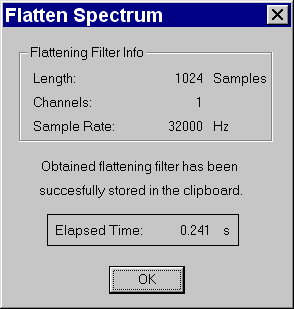 |
At this point the Imnverse Filter has been stored in the Windows Clipboard. Opening another instance of CoolEdit, and pasting from the Windows Clipboard, the following signal is recovered:
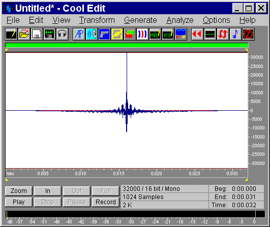 |
And looking at its frequency response, we obtain:
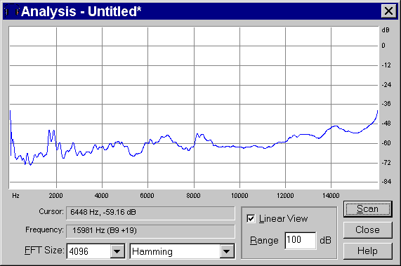 |
This is roughly the specular image of the original Impulse Response, and thus the recovered signal is the required equalising filter.
For verification, if we apply it by convolution to the original signal we obtain the following:
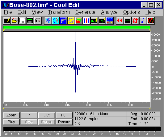 |
And looking at the frequency response we obtain:
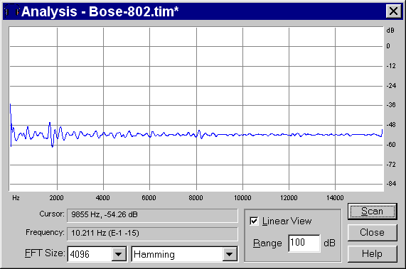 |
This is not perfectly flat, due to the limited number of taps employed for the creation of the Inverse Filter.
©2007 LAE